Grooved Pins
Grooved Pin Principle
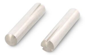
This fastener incorporates in its design three longitudinal grooves swaged or formed into a cylinder of material, which has the effect of increasing its diameter. In the case of unheaded pins, this may be over part or all of the length of the pin and may be of a tapered or parallel form. In the case of headed pins, the grooves are always parallel.
Groove compression
In each pin, installation of the grooved pin causes the grooves to compress, this compression produces outward pressure on the walls of the hole and in doing so secures location of the pin. Diagram 1 shows compression taking place as a section through a grooved pin.
Simple, Reusable, Resistant to Shock and Vibration
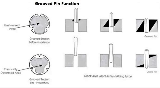
When compared with more traditional taper pins, plain pins, keys or locating pins which rely on ‘interference’ at one point on the pin and also require a reamed or precision formed hole, the grooved pin principle can be seen to represent a significant improvement.
Resistance to withdrawal occurs wherever the grooved diameter is compressed; it can be over the whole length of the pin instead of just at one point as with traditional pins. This advantage is represented in the image.
Advantages of using Grooved Pins
|
Simple Hole Preparation
|
No reaming or threading of the hole prior to installation is required |
|
Resistance to Shock and Vibration
|
Because the pin is held in position under elastic tension, it cannot easily be dislodged in harsh environments |
|
Wide Range
|
Standard pin types are available for many applications, eliminating the need for more labour intensive or complex fasteners, or custom designed expensive parts |
|
Reusable
|
When removed from the application, the grooves recover their form and can be reused many times with only minimal reduction in pull out performance |
|
Simple Installation
|
Once correct procedures are followed, there is no need for special installation equipment for small volumes. Where high production quantities are anticipated, the pin can easily be fed and does not require sophisticated installation equipment |
|
Strength and Corrosion Resistance.
|
The Grooved Pin is a solid stainless steel fastener giving high shear strength and good wear resistance |
Round Head Grooved Pins

DIN 1476 Round Head Grooved Pins (ISO 8746) have three equally spaced longitudinal tapered grooves that expand the pin’s diameter.
When inserted into the drilled hole of appropriate diameter the expanded diameter of the pin is pressed back to the nominal diameter. As the pin tries to expand to the larger diameter the force against the hole’s wall tightens the fit. This creates the holding power against shock and vibration.
 Combining the grooved pin principle with a headed stud makes it possible to use the fastening method for the retention of items in an assembly.
- Parallel grooves give maximum retention.
- For fixing name plates, panels, linings, pipe clips or any additional component to an assembly.
- Very rapid installation time shows a cost saving over conventional screws.
DIN 1476 Grooved Pins Round Head SS-304 A2 B4E08 – Download Datasheet
Grooved Pin with Full Length Taper Grooves

Original replacement for a conventional taper pin eliminating reaming of drilled holes thereby reducing machining time
Tapered grooves allow easy progressive installation.
Used as a locking pin, fixing pin or connecting pin.
Made as per DIN-1471 in Stainless Steel AISI 303
DIN 1471 Grooved Pins with Full Length Taper Grooves SS-303 B3E10 – Download Datasheet
Grooved Pin with Half Taper Grooves
 These pins have half taper grooves at one end which increases the pin’s diameter at that end.
Suitable for applications where a part of the assembly must be an easy fit.
Made as per DIN-1472 in Stainless Steel AISI 303
DIN 1472 Grooved Pins with Half Taper SS-303 B3E13 – Download Datasheet
Grooved Pin with Full Length Parallel Grooves

Maximum retention over whole length produced by full length parallel grooves
Suitable for applications involving longitudinal stress and vibration
Made as per DIN-1473 in Stainless Steel AISI 303
Replaces type DIN-1471 where improved performance is required.
DIN 1473 Grooved Pins with Full Length Parallel Grooves SS-303 B3E16 – Download Datasheet
Grooved Pin with Half Length Reverse Taper Grooves

Reverse taper groove eases installation into blind drilled holes.
Half length plain portion can be used as a drive element stop pin or bearing.
Plain portion can also be used as a handle replacing an expensive threaded component.
Made as per DIN-1474 in Stainless Steel AISI 303
DIN 1474 Grooved Pins with Half Length Reverse Taper Grooves SS-303 B3E09 – Download Datasheet
Grooved Pin with One Third Centre Groove
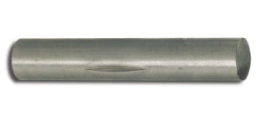 The one third centre groove locks the pin in place. The ends act as pivots.
These pics are used in hinges or as clevis pins or to create T-handles.
Made as per DIN-1475 in Stainless Steel AISI 303
DIN 1475 Grooved Pins with One Third Centre Groove SS-303 B3E12 – Download Datasheet
Installation Notes
- Hole Preparation. When drilling the hole for installation of a grooved pin, a standard twist drill should be used of the same nominal diameter as the ungrooved pin. Use hole tolerance H9 for pins under 3mm and H11 for 3mm and above, although in steel a slightly larger hole will only marginally affect withdrawal loads. Our Grooved Pins are produced with a minus tolerance on the ungrooved diameter to allow easy fit.
- Pin Strength. The tensile strength of the pin must be the same as or higher than the strength of the component material.

Installation. Parallel groove pins require significantly higher installation forces than tapered groove pins. To eliminate the chance of any difficulty during installation, a 60° counter sink should be incorporated into the hole and the pin should be slightly lubricated prior to installation. During installation it is important to ensure correct alignment between the pin and the hole.
When installing, apply a steady and even force, using tools like a press or mallet, to avoid pin damage or misalignment.
Avoid using excessive force as it may compromise the pin’s structural integrity or the fit itself.